Wire Colors
I may have messed up the colors when I originally measured colors for the wires for phase 1, phase 2, and phase 3.I used
| Phase 1 | red |
| Phase 2 | yellow |
| Phase 3 | blue |
| Ground | (none) |
Diodes in circuit
Resistance between phases and ground
| Phase 1 (red) | Ground | 8 Ω |
| Phase 2 (yellow) | Ground | 8 Ω |
| Phase 3 (blue) | Ground | 8 Ω |
Resistance between phases
| Phase 1 (red) | Phase 3 (blue) | |
| Phase 3 (blue) |
Inductance between phases and ground
It seems like I screwed up the decimal point and it should be 10.5 mH, not 105 mH
| Phase 1 (red) | Ground | |
| Phase 2 (yellow) | Ground | |
| Phase 3 (blue) | Ground |
Inductance between phases
| Phase 1 (red) | Phase 3 (blue) | |
| Phase 3 (blue) |
Capacitance between phases and ground
| Phase 1 (red) | Ground | |
| Phase 2 (yellow) | Ground | |
| Phase 3 (blue) | Ground |
Capacitance between phases
| Phase 1 (red) | Phase 3 (blue) | |
| Phase 3 (blue) |
Magnetic field general notes
When a phase wire is connected to the "+" side of the battery, the outside part of the coil pulls toward the South.
Magnetic field between phases and ground
| Phase 1 (red) Phase 3 (blue) | Ground | Direction |
| Connected to | ||
| - | + | |
| + | - | Outside of coil pulls south |
Magnetic field between phases
| Phase 1 (red) | Phase 3 (blue) | |
| Connected to | ||
| - | + | |
| + | - | |
| Phase 1 (red) | Phase 2 (yellow) | |
| Connected to | ||
| - | + | |
| + | - | |
| Phase 2 (yellow) | Phase 3 (blue) | |
| Connected to | ||
| - | + | |
| + | - | |
Magnets
The wheel or armature that spins has 36 magnets in it.
The magnetic fields alternate.
One magnet will have it's north field pointing up and the next magnet will have it's south field pointing up.
I used a magnet to verify that instead of the compass.
It was the magnet with one flat side and the other side was curved.
The flat side of the magnet stuck to every other magnet.
I can't tell if the wheel has a starting position or number one position.
Oddly there are 36 magnets, but only 27 coils.
There are 1.33 magnets for every coil.
There are 0.75 coils for every magnet.
Coils
The stator or non-moving part has 27 coils.
Each phase, i.e. phases 1 thru 3 has 9 coils.
All 9 coils for each phase are connected electrically.
The coils for the 3 phases are connected in a "Y" configuration. That is a "Y" configuration verses a "delta" configuration.
The center of the "Y" configuration is the ground wire. Phase 1 is the first arm of the "Y", phase 2 is the second arm of the "Y", and phase 3 is the bottom arm of the "Y".
You can run current thru:
| Phase 1 | to | Phase 2 |
| Phase 1 | to | Phase 3 |
| Phase 2 | to | Phase 3 |
In each of those cases you are running current thru 18 coils.
When you run current thru 2 different phases, the magnetic fields in each of the phases flip flops.
I.e. if you are running current thru phase 1 and phase 2, the outside of all the coils in phase 1 will have a north pole, and the outside of all of the coils in phase 2 will have a south pole or vice versa.
Oddly there are 36 magnets, but only 27 coils.
There are 1.33 magnets for every coil.
There are 0.75 coils for every magnet.
Coils vs magnets
There are 1.33 magnets for every coil.
There are 0.75 coils for every magnet.
Hall Effect firings per revolution
How many times are the Hall Effect sensors fired per revolution?
18 times for each phase
54 times for all 3 phases
We have 36 magnets on the rotating armature. We have 18 magnets on the rotating armature with the north pole up, and 18 magnets on the rotating armature with the south pole up.
We have 3 hall effect sensors mounted on the non-moving stator.
How many times are the hall effect sensors fired during one revolution of the motor?
During one revolution of the armature, the Hall Effect sensors each fire 18 times for each phase.
That is a total of 54 firings for all three hall effect sensors combined.
Remember while we have 36 magnets, 18 or half of them have their north poles facing up. The other 18 of them have south poles facing up.
The Hall Effect sensors are the type that only are triggered by one pole. I.e., they are either triggered by the north pole of the magnet, or the south pole of the magnet, but not both poles.
Since the magnets are installed with half of their north poles facing up and the other half with their south poles facing down, only half of the 18 magnets will fire the Hall Effect sensors. The other 18 magnets have their pole reversed and don't trigger the Hall Effect sensor.
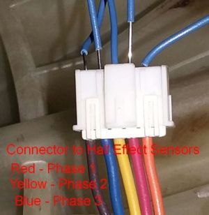
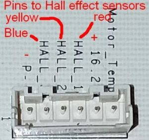
Wiring for Hall effect magnetic sensors
The signal names are from the printed circuit board on the machine.
The wire colors are from the connector that plugs into the printed circuit board.
| Signal Name |
Wire Color |
Phase Guess |
|---|---|---|
| temp | no wire | |
| 16.2 V | orange | |
| hall_1 | red | 1 |
| hall_2 | yellow | 2 |
| hall_3 | blue | 3 |
| P | brown |
I used the 3 colors of the wires that control the hall effect sensors for each phase to guess the colors of the power wires that drive each phase.
I suspect these are the colors and phases.
| Signal Name |
Wire Color |
Phase |
|---|---|---|
| hall_1 | red | 1 |
| hall_2 | yellow | 2 |
| hall_3 | blue | 3 |
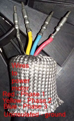
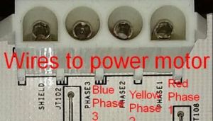
Power wires for driving the motor
| Wire Color |
Phase Guess |
|---|---|
| red | 1 |
| yellow | 2 |
| blue | 3 |
| uninsulated yellow/black |
ground |
1) the phases are just guesses,
based on the color of the wires
in the
hall effect table.
2) I don't have the original connector from the circuit board to the 3 sets if coils for phase 1, 2 and 3, so I made these guesses based on the color of the wires from the Hall effect sensors.
Red wire supplies current for phase 1, yellow wire supplies current for phase 2 and blue wire supplies current for phase 3.
The uninsulated wire is the ground wire.
The red wire sends current to phase 1. The yellow wire sends current to phase 2. The blue wire sends current to phase 2.
The uninsulated wire is the ground wire.
Hall effect sensors and wiring
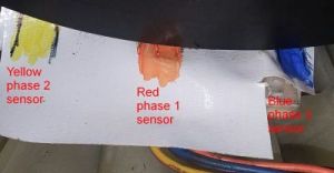
Location of hall effect sensors on the plastic hall effect assembly
|
Wire Color |
Position | Phase |
|---|---|---|
| blue | 11 O'Clock | 3 |
| red |
12 O'Clock center |
1 |
| yellow | 1 O'Clock | 2 |
Voltages hooked to hall effect sensors and wires
| Voltage | Wire color |
Signal Name |
|---|---|---|
| + | orange | +16.2 Volts |
| - | brown | ground |
| - | red | Phase 1 |
| - | yellow | Phase 2 |
| - | blue | Phase 3 |
When the Hall effect sensors turn ON they seem to be hooked to the negative side of the battery or ground. For some reason I thought it was the opposite of this. But I was wrong.
When the Hall effect sensors are turned OFF they seem to be not looked up to anything. I.e. They are NOT hooked up to the positive side, like I would expect a digital circuit to be.
I guess you could say when the Hall effect sensors they are in a NC or No Connect state.
Firing order of hall effect sensors.
As I turn the armature in a clockwise direction the hall effect sensors fire in this order. If I turn it in a counterclockwise direction the order is reversed.
|
Wire color |
Phase | Notes |
|---|---|---|
| red | 1 | |
| blue | 3 |
There is some overlap in the firing of the
blue (phase 3) & yellow (phase 2) hall effect sensors.
Maybe it's assembled cockeyed, maybe |
| yellow | 2 |
Confirmed location of Hall effect sensors
I played with the motor and confirmed which Hall effect sensors are attached to which phase and the color of the wires attached to each Hall effect sensor.
When the Hall Effect sensors are OFF, they seem to be hooked to the positive side of the battery and read about +5 volts.
When the Hall effect sensors are ON, they seem to be almost hooked to the negative side of the battery and only read about a tenth of a volts or around .1, or .15 volts.
| Location | Phase | Wire Color |
Suspected Firing Order |
|---|---|---|---|
|
Right clockwise |
2 | Yellow | 3 |
| Center | 1 | Red | 1 |
|
Left Counterclockwise |
3 | Blue | 2 |
Red wire is phase 1, yellow wire is phase 2 and blue wire is phase 3.
The orange wire is the positive or VCC and the grayish wires is negative or ground
P is the ground wire.
16.2 is the postive voltage or VCC.
The phase 1 Hall effect sensor is the red wire. The phase 2 Hall effect sensor is the yellow wire. The phase 3 Hall effect sensor is the blue wire.
Motor Temp is not connected.
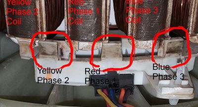
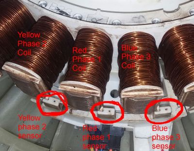
The right or most clockwise Hall effect senor is connected with the yellow wire for phase 2.
The center Hall effect senor is connected with the red wire for phase 1.
The left or most counterclockwise Hall effect senor is connected with the blue wire for phase 3.
The coil just to the right of each Hall effect sensor is a coil that is for the corresponding phase. I.e. the coil just to the right of the phase 1 sensor is a coil for phase 1, the coil just to the right of the phase 2 sensor is a coil for phase 2, and the coil just to the right of the phase 3 sensor is a coil for phase 3.
I don't know if the magnetic field generated by these coils effects the Hall sensor.
Do the coils turn on the Hall effect sensors?
Do the magnetic fields in the 3 sets of coils that drive the motor activate the Hall effect sensors? I.e. does the magnetic field from the Phase 1, 2, and 3 coils turn on the Hall effect sensors?
I only used the 10 volt battery JJ gave me to power them coils.
I used a coil and a 2nd battery JJ gave me to jack the voltage up to 20 volts.
In that test, the magnetic field of the coil was very week. Only about a fourth as strong as the magnet I had been using.
I suspect the solution is to jack up the voltage to 100 volts and see what happens.
It doesn't seem that way.
At least I couldn't get any repeatable, consistent results where the magnetic field from the coils seem to trigger the Hall effect sensors.
First I hooked up my test circuit which had 3 LEDs which are turned on each time a magnet passes a Hall effect sensor.
I tested the gizmo and the LEDs go on and off as the drum rotates and the magnets in the drum pass the Hall effect sensors.
Second I removed the drum to keep the magnets in it from activating the Hall effect sensors.
Third I hooked the positive side of the battery to each phase and the negative side of the battery to a different phase.
And I cycle thru running current thru each possible combination.
None of the tests turned on the test LEDs in a repeatable manner.
A couple of times the yellow LED turned on, but that seemed to be because of a short, or open circuit. I could not consistently get it to repeat.
I also ran current thru each phase and the ground wire. Again none of the tests turned on the Hall effect sensors.
Fourth and last I flipped the battery leads around and attached the positive and negative terminals of the battery to the opposite side.
Again I could not get any consistent result where the Hall effect sensors seem to be triggered by the magnetic fields in the phase 1, 2 or 3 coils.
Again, the yellow LED did go on several times, but I suspect it was a result of and intermittent short or open circuit. I could not get it to repeat on a consistent basis.
Why is the YELLOW LED for phase 2 so dim?
Why is the YELLOW LED for phase 2 much dimmer than the RED LED for phase 1 and the GREEN LED for phase 3?
I suspect that all 3 LEDs are pretty much the same intensity and it's just a matter of perception and our eyes precedence that the YELLOW LED is dimmer.
I replaced the YELLOW LED with a RED LED and the RED LED looked much brighter.
I measured the voltage across the 3 LEDs and they were all pretty close.
The voltage across the YELLOW and RED LEDs were almost identical. The difference was only about .017 volts or about 1/50 of a volt.
The difference between the YELLOW and GREEN LEDs was slightly higher, 0.589 volts or about .6 volts. Not sure why.
Voltage across LEDs
| LED Color | Voltage | Phase |
|---|---|---|
| Yellow | 1.691 | 2 |
| Red | 1.708 | 1 |
| Green | 2.280 | 3 |
Voltage difference between LEDs
| Voltage Differences | |||
|---|---|---|---|
| Yellow | Red | Green | |
| Yellow | 0.017 | 0.589 | |
| Red | 0.017 | 0.572 | |
| Green | 0.589 | 0.572 | |
Setting Motor Direction in an AC motor
Single phase vs 3 phase AC motors
For single phase motors it sounds like they have a starting cap, which is used to determine the direction the motor rotates
Good question. Does it matter the direction the washing machine motors turns???
I suspect it really doesn't matter.
For a spin cycle all you want to do is spin it really fast to squeeze the water out of the cloths. You don't care which direction it spins.
For normal washing, I suspect you just want to make the motor flip flop. Turn one way for a second, then turn the other way for a second.
And in that case you don't care about the order the motor moves in. Just as long as it flips direction every second or so.
Of course an AC motor that drives a saw or a drill, the direction would be very important.
You gotta spin it in the right direction to make the teeth cut.
SNIP
Definition of Start winding: in an A/C (alternating current) electric motor electrical current flowing through the start winding is used just to get the motor spinning from a stopped condition.
The start winding is disconnected, usually by a centrifugal switch, when the motor is up to speed.
Definition of Run winding: in an A/C electric motor the run winding is what keeps the motor spinning once it has started.
Current flowing through this winding produces a rotating magnetic field in the stator that keeps the motor shaft turning after the start winding has turned off.
Electric motor start switch: a centrifugal switch connects the A/C electrical power to the motor to the start winding on the stator until the motor has reached a speed typically of 75-80% of its full run speed (typically that's1725 rpm or 3450 rpm on newer high-speed oil burners).
SNIP
In a fixed-direction electric motor such as on an HVAC blower fan or an A/C or heat pump compressor, each time the motor starts its start capacitor and start winding give the motor a "kick" in the right direction.
[OK, where are these magic "start caps" and "start windings"]
SNIP
Reversing the direction of a 3 phase motor can be done by swapping the connection of any two phases. [All the other articles agree with this. So it sounds like the direction of a 3 phase motor is determined by the firing order of the phases]
SNIP
Reversing the direction of a 3 phase motor can be done by swapping the connection of any two phases. [or in my case by the software]
The same article also explains how the motor is forced to start in one direction
SNIP
A single phase motor has 2 windings electrically located at 90 degrees apart. One is designed to magnetize earlier than the other by using a capacitor or by using thinner wire for the windings depending upon the type of motor it is..
The winding with a capacitor in series will magnetize slightly earlier than the winding without the capacitor. So what happens is there appears to be a moving magnetic field in the first part of each half cycle. This determines the direction the rotor starts to rotate. When the rotor is running at nearly full speed a speed sensing mechanism disconnects the start winding. The motor will continue to run. [I wonder, does this mean one magnetic field is weaker than the other and the stronger magnetic field forces the motor in a specific direction?]
SNIP
For multiple phase motors and the [sic] means three, it's the order of how the three phases are wired… it rotates the direction of the phase rotation.
Here is another blurb on how single phase motors figure out which direction to spin. It's worded slightly different
SNIP
A capacitor in series with the start wiring produces a phase shift , or a shorted (shaded) turn exploits magnetic effects to produce a phase shift.
[I think what they are saying is the cap causes the magnetic field in one set of coils to be slightly out of sync with the magnetic field in the other coil, and thus forces the motor to rotate in a specific direction at start time - gotta think about that in my brain for a second or two]
[Or maybe as I said before is one magnetic field weaker than the other magnetic field and that forces the motor to spin in a specific direction?]
One more article on how an AC motor figures out it's direction at start time
SNIP
To reverse rotation on a single phase capacitor start motor, you will need to reverse the polarity of the starter winding. This will cause the magnetic field to change directions, and the motor will follow. In order to achieve this, you can swap the connections on either end of the winding.
SNIP
On Sunday, July 14, 2019 JJ gave me two documents on this and I used them to do these calculations.
Those articles are titled
CD-ROM Sensored BLDC motor control with Arduino - Simple ProjectsSensored brushles DC motor control with Arduino - Simple Projects
There are two items on this.
First you can use the 3 hall effect sensors, which if you use 1 for on and 0 for off you can use to generate a binary number of 1 thru 6 for each of the 6 steps you cycle thru on a rotation of the motor.
Second for each of those 6 steps you have for the pins that send voltage to the motors
1 pin or phase will be set to (+) or a positive voltageAlso in those two article they call the phases A, B, and C instead of phase 1,2, and 3.1 pin or phase will be set to (-) or a negative volatage
1 pin or phase will not be turned on.
You can use the 3 numbers from the hall effect sensors to generate a binary number of 1 to 6 to tell which phases of the motor to turn on.
In these two article the phases are labeled A, B and C rather then 1, 2 and 3 in the other documentation.
The number is a 1 or one if the hall effect sensor is on and 0 or zero if the hall effect sensor is off.
| Hall Effect Sensor | Step # | ||
|---|---|---|---|
| C | B | A | |
| 0 | 0 | 1 | 1 |
| 0 | 1 | 0 | 2 |
| 0 | 1 | 1 | 3 |
| 1 | 0 | 0 | 4 |
| 1 | 0 | 1 | 5 |
| 1 | 1 | 0 | 6 |
These are the voltages applied to each pin or phase.
| Table 20 | |||
|---|---|---|---|
| Step # | Voltage for phase | ||
| A | B | C | |
| 1 | + | - | |
| 2 | - | + | |
| 3 | + | - | |
| 4 | - | + | |
| 5 | + | - | |
| 6 | - | + | |
The data in I calculated in the previous two tables are from page 2 of the articles I mentioned above.
Related URLs
Firing 2 pins and then firing 1 pin
This is done 6 times per revolution.
I.e, phase 1 & 2 will be fired at the same time with phase 1 being hooked to positive and phase 2 hooked to negative.
Then that is repeated for phase 1 & 3, and finally for phase 2 & 3.
Then for the next 3 cycles of the 6 cycles in a revolution, positive and negative will be reversed for the connections.
Such as in the prior example in table 20.
Here table 20 is shown again.
| Table 20 | |||
|---|---|---|---|
| Step # | Voltage for phase | ||
| A | B | C | |
| 1 | + | - | |
| 2 | - | + | |
| 3 | + | - | |
| 4 | - | + | |
| 5 | + | - | |
| 6 | - | + | |
This video and web page describes a slightly different scheme where in 3 of the 6 cycles, current is run thru 2 of the phases at t he same time.
I.e. run current thru A to B, A to C and B to C. Or perhaps from A & B to ground, A & C to ground and finally B & C to ground.
While in the remaining 3 of the 6 cycles current is only run thru one of the phases at a time.
I.e. run current thru only A, B or C.
And in these 3 cases the only place for the current to leave A, B or C is via the ground wire.
From the website and video, I couldn't figure out which phases were hooked to positive, negative or ground, so I just put an X in the cell to show it was being used.
Which gives us this table 21, which is a slightly modified version of table 20.
| Table 21 | |||
|---|---|---|---|
| Step # | Voltage for phase | ||
| A | B | C | |
| 1 | X | X | |
| 2 | X | ||
| 3 | X | X | |
| 4 | X | ||
| 5 | X | X | |
| 6 | X | ||
Voltage Levels
Voltage reading on Arduino boards
| Power Supplies | |
|---|---|
| Type | Volts |
| USB Power Supply | 4.99 |
| Mega A/C Power Supply | 9.83 |
| Voltages on Arduinos | |||
|---|---|---|---|
| Model | |||
| Pins | Volts | Volts | |
| From | To | USB Supply | A/C Supply |
| UNO - China version | |||
| VIN | Ground | 4.42 | 8.64 |
| 5V | Ground | 4.95 | 4.98 |
| 3.3V | Ground | 3.29 | 3.30 |
| UNO - OSEPP | |||
| VIN | Ground | 4.42 | 8.62 |
| 5V | Ground | 4.91 | 4.99 |
| 3.3V | Ground | 3.29 | 3.29 |
| MEGA | |||
| VIN | Ground | 4.38 | 8.61 |
| 5V | Ground | 4.91 | 4.99 |
| 3.3V | Ground | 3.35 | 3.35 |
Motor Tests
Magnet location NOT considered
Using Phase X to the ground wire
Actually I didn't delete them, I just marked them as comments and they are still on this web page. You can see them if you remove the two lines that make them as comments. I.e the
<!--&
-->
Motor Tests
Magnet location CONSIDERED
Using Phase X to the ground wire
In each case the red line taped to the drum near the C was started next to L1, L2, or L3 and I tested the direction it rotated in.
7) Negative hooked to ground
| Ground hooked to Negative (-) | |||
|---|---|---|---|
| Phase | L1 | L2 | L3 |
| Yellow | Counterclockwise | Clockwise | |
| Red | Clockwise | Counterclockwise | |
| Blue | Clockwise | Counterclockwise | |
8) Positive hooked to ground
| Ground hooked to Positive (+) | |||
|---|---|---|---|
| Phase | L1 | L2 | L3 |
| Yellow | Clockwise | Counterclockwise | |
| Red | Clockwise | Counterclockwise | |
| Blue | Counterclockwise | Clockwise | |
Magnet location CONSIDERED
Using Phase X to Phase Y - Ground wire not used
In each case the red line taped to the drum near the C was started next to L1, L2, or L3 and I tested the direction it rotated in.
Test 9 - Positive hooked to Phase X, negative hooked to Phase Y
This table should essentially be the same as Test 10 reversed or flipped. And it seems to be.
I had problems measuring the 4 cells with a background color of yellow.
|
Phase X + |
Phase Y - |
L1 | L2 | L3 |
|---|---|---|---|---|
| Yellow | Red | Clockwise | Counterclockwise | |
| Yellow | Blue | Counterclockwise | Clockwise | |
| Red | Yellow | Clockwise | Counterclockwise | |
| Red | Blue | Counterclockwise | Clockwise | Counterclockwise |
| Blue | Yellow | Clockwise | Counterclockwise | |
| Blue | Red | Clockwise | Counterclockwise | |
Test 10 - Negative hooked to Phase X, positive hooked to Phase Y
This table should essentially be the same as Test 9 reversed or flipped. And it seems to be.
I had problems measuring the 4 cells with a background color of yellow.
|
Phase X - |
Phase Y + |
L1 | L2 | L3 |
|---|---|---|---|---|
| Yellow | Red | Clockwise | Counterclockwise | |
| Yellow | Blue | Clockwise | Counterclockwise | |
| Red | Yellow | Clockwise | Counterclockwise | |
| Red | Blue | Clockwise | Counterclockwise | |
| Blue | Yellow | Counterclockwise | Clockwise | |
| Blue | Red | Counterclockwise | Clockwise | Counterclockwise |
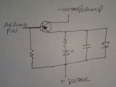
Transistor to drive motor
Test 11
In this test I build a board that which the Arduino board turns a transistor on and off to drive the motor.
In the first part I used the 5 volt power supply from the Arduino board to drive the whole circuit.
In the 2nd part I used a 10 volt battery to drive the circuit.
The first part works perfectly and the LED goes on and off every 2 seconds. That's 100% on and 100% off.
When the LED is ON the voltage across it is about 5 volts or really 4.39, which is OK. When the LED is OFF, the voltage across it is about a half volt, which is OK with me.
The second part kinda sorta works in that the the LED goes on and off every 2 seconds.
But the LED does not go 100% off. That's the problem.
When the LED is on the voltage across it is about 10 volts which is OK.
The problem is when the LED is off, the voltage across it is about a 5 volts. That 5 volts is enough to brightly light the LED.
I'm kind of confused whey the voltage is so high.
I suspect an opto-isolator chip will fix the problem. But I suspect my circuit is poorly designed and something is wrong with the logic.
I tried using a 100 ohm, 10K ohm and 2 mega ohm resistor to tie the transistor to the positive side, but that didn't work.
When the Arduino board is being used along, the Arduino +5 volts was hooked to the + voltage and the Arduino ground was hooked to the - voltage ground.
When the Arduino was used in conjunction with a 10 volt power supply, the positive side of the 10 volt power supply was hooked to the + voltage and the negative side power supply to the - voltage ground.
When the Arduino was used in conjunction with a 10 volt power supply. ONLY the Arduino ground was hooked to the - voltage ground. The Arduino +5 volts was not hooked to the circuit. And of course the Arduino pin was hooked to the base of the transistor.
|
Arduino 5
volt Supply |
10 volt Supply |
|
|---|---|---|
| Power Supply voltage | 4.88 volts | 10.06 volts |
| Base ON | .96 volts | .24 volts |
| Base OFF | 4.90 volts | 4.90 volts |
| Output ON | 4.39 volts | 10.06 volts |
| Output OFF | .47 volts | 5.22 volts |
Op Amp tests - Operational Amplifier Tests
LM741 +10 volt test - 10 volts total
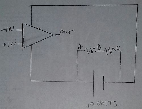
| - in | + in | Output Volts |
Expected Volts |
|---|---|---|---|
| NC | NC | 9.3 | ? |
| A | NC | 9.3 | ? |
| A | A | 9.3 | 0 |
| A | B | 9.3 | + |
| A | C | 9.3 | + |
| B | NC | 1.8 | ? |
| B | A | 1.8 | - |
| B | B | 1.9 | 0 |
| B | C | 9.3 | + |
| C | NC | 1.8 | ? |
| C | A | 1.8 | - |
| C | B | 1.8 | - |
| C | C | 1.8 | 0 |
LM741 +20 volt test - +10 volts & -10 volts
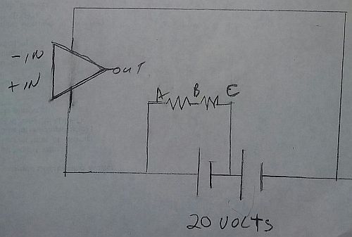
| - in | + in | Output Volts |
Expected Volts |
|---|---|---|---|
| NC | NC | 8.4 | ? |
| A | NC | -8.0 | ? |
| A | A | -7.9 | 0 |
| A | B | +10.5 | + |
| A | C | +10.5 | + |
| B | NC | -8.2 | ? |
| B | A | -8.2 | - |
| B | B | -7.8 | 0 |
| B | C | +10.4 | + |
| C | NC | -8.0 | ? |
| C | A | -8.3 | - |
| C | B | -8.2 | - |
| C | C | +10.4 | 0 |
LM7358N +10 volts only
The tests for op amp A & op amp B seemed consistent for the tests of B & C.
The tests for op amp B, for the A tests also seemed good.
I did I flip the labels for -in & +in?
| - in | + in | Output A Volts |
Output B Volts |
Expected Volts |
|---|---|---|---|---|
| NC | NC | 0 | 8.7 | ? |
| A | NC | 0 | 8.7 | ? |
| A | A | 0 | 8.7 | 0 |
| A | B | 0 | 0 | + |
| A | C | 0 | 0 | + |
| These 2 0 valuew look wrong. I suspect they should be 8.7, the same as for output B.
Why? I don't know. Is op amp A broken? |
||||
| B | NC | 8.7 | 8.7 | ? |
| B | A | 8.7 | 8.7 | - |
| B | B | 0 | 0 | 0 |
| B | C | 0 | 0 | + |
| C | NC | 8.7 | 8.7 | ? |
| C | A | 8.7 | 8.7 | - |
| C | B | 8.7 | 8.7 | - |
| C | C | 8.7 | 8.7 | 0 |
LM7386 +10 volts only
| - in | + in | Output Volts |
Expected Volts |
|
|---|---|---|---|---|
| NC | NC | 5.3 | ? | |
| A | NC | .5 | ? | |
| A | A | 10.0 | 0 | |
| A | B | .5 | + | |
| A | C | .5 | + | |
| B | NC | .5 | ? | |
| B | A | 10.0 | - | |
| B | B | .9 | 0 | |
| B | C | .5 | + | |
| C | NC | 5.7 | ? | |
| C | A | 10.0 | - | |
| C | B | 10.0 | - | |
| C | C | 5.7 | 0 | |
Amps or current thru the washing machine motor
Amps running thru washing machine motor
| Test | Amps | % |
|---|---|---|
| Running motor from battery | 0.66 | 100% |
| Mike's circuit | 0.06 | 9% |
| JJ's circuit (2K resistor at base) | 0.16 | 24% |
| JJ's circuit (800 resistor at base) | 0.40 | 60% |
JJ's final circuit
Circuit to allow Arduino to talk to washing machine motor

Strange measurements from the Hall Effect sensors
Measuring via ground & Hall effect sensor and +16.2 volts & Hall effect sensor
In the past when I measured the voltage from the Hall Effect sensors, I measured the voltage between the Hall effect sensor and the ground wire.
JJ suggested that I measure the voltage instead of between the round wire, measure it between the Hall effect sensor and the 16.2 volt write.
These measurements were rather strange and odd.
The ground write is the brown wire on the side.
The 16.2 volt wire is the orange wire on the other side.
The 3 hall effect sensor wires are the 3 wires in the middle and are red, yellow and blue wires.
In this test I used the board I build with the 3 LEDs and the 7805 voltage regulator on it to do the tests
| Testing with 12 volt battery | ||
|---|---|---|
| Hall Effect Sensor |
Volts
ground or brown wire |
Volts
16.2 volts or orange wire |
|
Source Voltage Between brown & orange wires |
|
|
| Red Wire |
3.53
Green LED |
4.82
Yellow LED |
| Yellow Wire |
3.69
Yellow LED |
4.92
Red LED |
| Blue Wire |
3.40
Red LED |
4.92
Greem LED |
Wow - Seems like +16.2 is the Ground
The Arduino is now driving the Hall effect sensors
The only odd thing, is that the POSITIVE voltage or 16.2 voltage signal is used for the ground.
I bet I accidently used this logic when I initially tested the Arduino and that's why it worked.
| Testing with Arduino via 120 volt power supply | ||
|---|---|---|
| Hall Effect Sensor |
Volts
ground or brown wire |
Volts
16.2 volts or orange wire |
|
Source Voltage Between brown & orange wires |
|
|
| Red Wire | NONE | 5.00 |
| Yellow Wire | NONE | 5.00 |
| Blue Wire | NONE | 5.00 |
| Testing with Arduino via USB power supply | ||
|---|---|---|
| Hall Effect Sensor |
Volts
ground or brown wire |
Volts
16.2 volts or orange wire |
|
Source Voltage Between brown & orange wires |
|
|
| Red Wire | NONE | 4.98 |
| Yellow Wire | NONE | 4.99 |
| Blue Wire | NONE | 4.98 |
Notes on what I did to fix the problem.
I'm going to modify that code to read all 3 hall sensors.
EURIKA - Plus is ground, Ground is Plus for some reason I was assuming that the output of the hall effect pins was relative to the ground, "-", or minus wires
that is NOT true
the output of the hall effect pins is relative to the +16.2 volt, "+", or positive wire
so make your voltage measurements between the orange wire (16.2 volts) and the corresponding hall effect wire i.e. red, yellow, or blue
dont measure voltage between the brown wire (ground) and the corresponding hall effect wires i.e. red, yellow or blue
also when hooking the hall effect wire to the arduino board, you have to put in a pull up resistor to the positive, "+", or 16.2 volt side.
when I ran the hall effect sensors on the motor with my 12 volt battery, the Aduino powered by a 120 volt wall socket and the Arduino powered by the USB drive voltage I got these measurements
|
hall effect wire |
ground wire brown |
positive 16.2 volt orange |
|---|---|---|
| RED | NONE | 5 volts |
| YELLOW | NONE | 5 volts |
| BLUE | NONE | 5 volts |
so it seems like when the hall effect sensors go on they get 5 volts relative to the signal name of 16.2 volts which is the positive orange wire on the motors hall effect wires
im going to make 3 versions of this program for JJ
|
TEST 1
on the first test I hooked the output from the hall effect directly to the input pin i didnt put any pull up or pull down resistors
i was getting intermittent results
for every time i rotated the motor I should get something like 18 changes i.e. 9 changes for the hall effect sensor turning on and 9 changes for the hall effect sensor going off
on one rotation i got 9 changes
on one rotation i got 7 changes
on one rotation i got 2 changes
several possible problems
1) the hall effect sensors are working intermetantilly2) the hall effect sensors are NOT working and the changes on the pins are being triggered by static electricity
3) I need to put some pull up or pull down resistors into the circuit to default the sensors to either a high/low, true/false or 1/0.
TEST 2
in this case when I move the motor to a position where a sensor is OFF, the input stablized and it returns a constant value of false
but when I move the motor to a position where a sensor is, it goes nuts and constantly turns the sensor on and off.
i suspect this is being cause by it picking up static electricity and turning on and off
i suspect in the second position where it's looping i can fix that problem by adding a pull up or pull down resistor to the board to default the input to either true or false
TEST 3
finally it seems to be working
for this test i added a pull up resistor to the input pin to default it to plus, true or 1
if you don't know what a pull up resistor is i hooked a 10,000 Ω ohm resistor to the positive side. then hooked the hall effect sensor to the 10,000 Ω ohm resistor. then I hooked the input for the hall effect pin on the arduino board to that mess.
so the Adruino pin, the wire from the motor for hall effect sensor x, and the 10,000 Ω ohm resistor are all hooked together.
the other side of the 10,000 Ω ohm resistor is hooked to the positive rail
and of course the input for the Arduion hall effect pin is also hooked to HALL_EFFECT_SENSOR_A which at this time is pin 2 on the Arduino board
when I spin the motor for one revolution i get 36 changes which seems to be a reasonable number
on the second spin it jumped to 72 changes which also seems pretty reasonable
on the third spin I the number jumped to 108, which again is a nice mutiple of 108 and on t he 4th spin it's up to 146, which again is amost a nice multiple of 36

Coils trigger hall effect sensors?
JJ suspects the coils are triggering the hall effect sensors
Hall effect sensors are "latching"?
JJ also thinks that when the "hall effect" sensors turn on they are latching, or turning on and staying on until they are turned off by a magnetic field of the opposite direction.
I.e. if a "hall effect" sensor is turned on by a north magnetic field, it has to be turned off by a south magnetic field.
JJ seems to be right
In my tests JJ seems to be right in both cases.
While in my tests I could get the "hall effect" sensors to "latch" I couldn't figure out how to get them to consistently "latch".
When I ran current thru the coils, which include all 3 coils, i.e. the phase A, B and C coils, or phase 1,2 and 3 coils, I could get the coils to consistently make the "hall effect" sensors turn on and off.
I ran current thru the single coils to ground.
I rain current thru the coils in pairs.
And I ran current in both directions flipping the positive and negative sides of the battery.
And in all cases I could get the coils to trigger the "hall effect" sensors.
Arduino C program - jj_mike_017_coils_change_sensors()
For the tests I wrote a C program for the Arduino computer which is
jj_mike_017_coils_change_sensors()
The computer program just monitors the 3 "hall effect" sensors and displays a message on the debug screen when they change.
The computer program also has 3 debug lights on a breadboard that it turns on and off when the "hall effect" sensors go on and off.
Those are the red, green and yellow LEDs, which correspond to the red, yellow and blue "hall effect" sensor wires.
The red, yellow and blue "hall effect" sensor wires correspond to "hall effect" sensors A, B and C in that order. The are also called phase 1, 2 and 3, again in that order.
| Phase | Wire | LED | |
|---|---|---|---|
| 1 | A | red | red |
| 2 | B | yellow | yellow |
| 3 | C | blue | green |
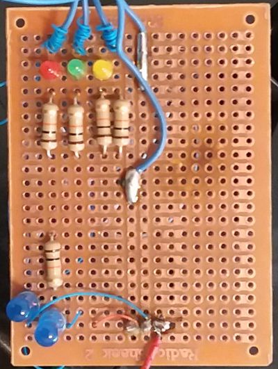
Breadboard
The breadboard I designed has 3 LEDs which are powered by the Arduino and turned on and off in correspondence with the "hall effect" sensors being turned on and off.
Each LED has a 10,000 ohm resistor to keep it from burning out with too much current.
The breadboard also has 3 inputs from the "hall effect" sensors which are passed on to the Arduino.
Each of the "hall effect" sensors has a 10,000 ohm pull up resistor to default the hall effect sensor to true, on, or 1.
You would figure the default would be low, false or 0, but it's the opposite.
That looks like:
|
+5 volts Arduino |
-------- |
10,000 ohm resistor |
-------- |
Connector to Arduino Hall Effect input |
-------- |
connector to motor hall effect sensor output |
Tests Done
For this stuff I did two sets of tests with magnets on the "hall effect" sensors.
The first tests simply used magnets to turn the 3 hall effect sensors on and off.
The second tests tried used magnets to attempt to turn on the hall effect sensors and "latch" or stay on.
Next I did two more sets of tests running current thru the coils attempting to get the hall effect sensors to turn on/off and or latch.
One set of tests ran current thru a single coil via ground.
The other tests ran current thru two coils, by passing the ground.
Both sets of tests ran current both ways flipping negative and positive around.
Magnets turn hall effect sensors on/off
It seems like the "hall effect" sensors are polarized and react to one either the north or south field to turn on or off and react to the other pole to flip flop states.
But I didn't attempt to document which pole does what.
Most of the time I would play with this magnet, which has it's north pole on the flat side.
Magnets uses to make "hall effect" sensors "latch"
I was also able to move a magnet by all of the 3 "hall effect" sensors and get the "hall effect" sensor to "latch" and stay on. And then later turn off or unlatch by again moving a magnet by it.
It seems like the "hall effect" sensors are polarized and either the north or south field causes the "hall effect" sensor to turn on and stay turned on. Moving the other magnet pole by it causes the "hall effect" sensor to "unlatch" and turn off.
I didn't attempt to document which pole causes the "hall effect" sensor to turn on or latch on, and which pole causes the "hall effect" sensor to turn off or unlatch.
Magnets tested on iron core of coils next to "hall sensors"
I was also able to turn the "hall effect" sensors on and off by attaching a magnet to the iron core which the coils are wound around.
I attached the magnet to the iron core above and to the left of the "hall effect" sensor.
I was also able to get the "hall effect" sensors to latch on and off, by attaching a magnet to iron core which the coils are wound around.
I could reliable get a "hall effect" sensor to turn off or "unlatch" by flipping the magnet around and attaching the magnets other pole to the iron core which the coils are wound around.
So it seems almost certain that the "hall effect" sensors are polarized.
Running current does turn on "hall effect" sensors
I did 4 more tests and ran current thru the coils to see the current could get the "hall effect" sensors to turn on.
In all 4 tests I ran running current thru the coils I could get the "hall effect" sensors to turn on and off.
In the first tests I ran current from phase A, B and C to ground. Or phase 1, 2, and 3 to ground.
Then I flipped the polarity of the battery and ran current the opposite way.
I used JJ's 10.1 volt battery pack to do the tests.
In all the tests I could get the "hall effect" sensors to turn on.
In the second tests I ran current from phase A to B, A to C and B to C.
Then I flipped the polarity of the battery and ran current the opposite way.
I used JJs 10.1 volt battery pack to do the tests.
In all the tests I could get the "hall effect" sensors to turn on.
More tests on running current thru motor
Yes running current thru the motor does turn on hall effect sensors
play_mike_182()
or
jj_mike_018_find_firing_order()
1) First I rotated the drum to verify the hall effect sensors were firing as the drum rotated.
The hall effect sensors were firing in this order
2) Next I used JJ's 10.1 volt battery pack to run current thru the motor wires to ground.
In all of the tests I did when current was run thru the motor wires it did cause the hall effect sensor to turn on and fire.
TEST 1
For the first test I moved the rotor until hall effect sensor 1 (A) fired.
Next I ran current thru the red, yellow and blue motor wires to ground.
In all 3 of the tests, the current caused the hall effect sensors to fire.
TEST 2
For the second test I moved the rotor until hall effect sensor 2 (B) fired.
Next I ran current thru the red, yellow and blue motor wires to ground.
In all 3 of the tests, the current caused the hall effect sensors to fire.
I got bored and didn't repeat the test for the next 4 combinations, which are
3 (AB) 4 (C) 5 (AC) 6 (BC)
Running the motor
Direction current needs to flow to run the motor forward and backward
I think that there will always be either one or two hall effect sensors turned on at a time.
There will NEVER be 3 hall effect sensors turn on at the same time.
I suspect there will always be at least one hall effect sensor turned on. But I haven't proven that.
I used the terms phase A, B and C interchangeability with phase 1,2 and 3.
So phase 1 is the same as phase A.
The RED wire is phase 1 or A, the YELLOW wire is phase 2, or B, and the BLUE wire is phase 3 or C.
Those are the color of the wires that read the status of the hall effect sensors and supply current to the motor coils.
| A hall effect sensor is on | |||
| Battery Connection | Motor rotation | ||
| + A | - Ground | Clockwise | |
| - A | + Ground | Counterclockwise | |
| + B | - Ground | Counterclockwise | |
| - B | + Ground | Clockwise | |
| + C | - Ground | Counterclockwise | |
| - C | + Ground | Clockwise | |
| B hall effect sensor is on | |||
| Battery Connection | Motor rotation | ||
| + A | - Ground | Counterclockwise | |
| - A | + Ground | Clockwise | |
| + B | - Ground | Clockwise | |
| - B | + Ground | Counterclockwise | |
| + C | - Ground | Counterclockwise | |
| - C | + Ground | Clockwise | |
| C hall effect sensor is on | |||
| Battery Connection | Motor rotation | ||
| + A | - Ground | Counterclockwise | |
| - A | + Ground | Clockwise | |
| + B | - Ground | Counterclockwise | |
| - B | + Ground | Clockwise | |
| + C | - Ground | Clockwise | |
| - C | + Ground | Counterclockwise | |
| A & B hall effect sensors are on | |||
| Battery Connection | Motor rotation | ||
| + A | - Ground | Clockwise | |
| - A | + Ground | Counterclockwise | |
| + B | - Ground | Clockwise | |
| - B | + Ground | Counterclockwise | |
| + C | - Ground | Counterclockwise | |
| - C | + Ground | Clockwise | |
| A & C hall effect sensors are on | |||
| Battery Connection | Motor rotation | ||
| + A | - Ground | Clockwise | |
| - A | + Ground | Counterclockwise | |
| + B | - Ground | Counterclockwise | |
| - B | + Ground | Clockwise | |
| + C | - Ground | Clockwise | |
| - C | + Ground | Counterclockwise | |
| B & C hall effect sensors are on | |||
| Battery Connection | Motor rotation | ||
| + A | - Ground | Counterclockwise | |
| - A | + Ground | Clockwise | |
| + B | - Ground | Clockwise | |
| - B | + Ground | Counterclockwise | |
| + C | - Ground | Clockwise | |
| - C | + Ground | Counterclockwise | |
Running the motor ONE coil at a time
Running the motor 1 coil at a time in a clockwise direction
| Step |
Hall Effect Sensor(s) |
Coil to energize |
|---|---|---|
| 1 | B | +B → -Ground |
| 2 | A & B | +B → -Ground |
| 3 | A | +A → -Ground |
| 4 | A & C | +A → -Ground |
| 5 | C | +C → -Ground |
| 6 | B & C | +C → -Ground |
Running the motor TWO coils at a time
Running the motor 2 coils at a time in a clockwise direction
In the case the ground is not used and the current runs from phase A to phase B or whatever.
And I said I THINK. I'm not 100% positive.
| Step |
Hall Effect Sensor(s) |
Coils to energize |
|---|---|---|
| 1 | B | +B -C |
| 2 | A & B | +B -C |
| 3 | A | +A -B |
| 4 | A & C | +A -B |
| 5 | C | +C -A |
| 6 | B & C | +C -A |
or
| Step |
Hall Effect Sensor(s) |
Coils to energize |
|---|---|---|
| 1 | B | +B -A |
| 2 | A & B | +B -C |
| 3 | A | +A -C |
| 4 | A & C | +A -B |
| 5 | C | +C -B |
| 6 | B & C | +C -A |
Questions
You gave me several sets of software and instructions to drive the 3 phase motor which you got off of the web. They all drive the 3 phase motor a lot differently then the logic you use.
In your logic you always have current running thru all 3 phases of the motor at the same time. I.e. you are always running current thru A, B and C to the ground terminal.
In their logic they only run current thru 2 phases of the motor at any given time. I.e. they only turn current thru A to B, A to C, or B to C.
I still have the software I wrote and we have never really used it or tested it.
If you want I'm willing to tweek the software and test it using their method of driving the motor.
They have 6 different steps for driving the 3 phase motor based on the hall effect sensors.
Their six steps of logic are:
- When hall effect sensor A goes on by itself attach phase A of the motor to the + side of the battery and phase C of the motor to the - side of the battery.
- When hall effect sensor B goes on by itself attach phase B of the motor to the + side of the battery and phase A of the motor to the - side of the battery.
- When hall effect sensors A & B go on together attach phase B of the motor to the + side of the battery and phase C of the motor to the - side of the battery.
- When hall effect sensor C goes on by itself attach phase C of the motor to the + side of the battery and phase B of the motor to the - side of the battery.
- When hall effect sensors A & C go on together attach phase A of the motor to the + side of the battery and phase B of the motor to the - side of the battery.
- When hall effect sensors B & C go on together attach phase C of the motor to the + side of the battery and phase A of the motor to the - side of the battery.
Note that all 3 hall effect sensors A, B and C NEVER go on at the same time.
Also all 3 hall effect sensors A, B and C NEVER go off at the same time.
This is one of the URLs that you gave me that describe all this stuff:
http://simple-circuit.com/arduino-bldc-brushless-...
This is a table or diagram that I sent you an a prior email that describe the relationships I described in steps 1 thru 6 previously. I made it from the data in the several articles you gave me and the software you gave me.
| Phase | hall effect sensor | Voltage to put on phase i.e. + or - | |||||||
| C | B | A | C+ | C- | B+ | B- | A+ | A- | |
| 6 | 1 | 1 | 1 | ||||||
| 4 | 1 | 1 | 1 | ||||||
| 5 | 1 | 1 | 1 | 1 | |||||
| 2 | 1 | 1 | 1 | ||||||
| 1 | 1 | 1 | 1 | 1 | |||||
| 3 | 1 | 1 | 1 | 1 | |||||
Answers
my first reaction is that the halls are always on.... when they are powered up on the red and black with 5 volts. if its plus 5 volts out, north is near, if its 0 volts, or gnd, south is near. so if its north near you want the solenoid string of 9 the north is approaching to be SOUTH, and pull the north magnets toward it.
so if the blue hall is plus 5 and that indicates a north perm mag is just approaching, you want the blue power lead to the Y to be powered to make a SOUTH pole on the 9 solenoids. so the rule is the hall just shows north approaching then turn on the same color 9 solenoid string south. and vice versa.
this leads to 6 rules. if hall blue is north then blue string of nine is south , if hall blue is south, then blue string is north, if hall red is north then red string is south, if hall red is south then red string is north, if hall yellow is north then hall string yellow is south, if hall yellow is south then hall string yellow is north.
has to be that way ipso facto qed. its because the hall sensor precedes the solenoid string so that the voltage sent to the string will pull the perms toward it.
now there is an important corollary, and that is when the hall changes sign, the power must be shut down EARLY to capture the EMF. so there might be a short period, millisecs, in which the solenoid string is not powered and the emf pulse is routed to a trap (my zener bridge for example, dumping into a big polarized cap). there are also schottkey diodes that may apply here.
Ok, enough for now, but this picture is complicated by the fact that we are not using the center of the y as ground, but the other colored phases. i will try to deal with your binary chart tomorrow.
jim
This is from a document JJ gave me located at:
From the table or diagram in Figure 3 it sounds like phase A, B and C are out of sync with each other by one cycle. I used figure 3 to create the following table.
Each phase begins with two "+" pulses, followed by a single "0" pulse, followed by two "-" pulses, followed by a final "0" pulse.
That means there are 6 pulses or steps for all 3 phases.
| Cycle | |||||||||
| Phase | 1 | 2 | 3 | 4 | 5 | 6 | 7 | ||
| A | + | + | 0 | - | - | 0 | + | ||
| B | - | 0 | + | + | 0 | - | - | ||
| C | 0 | - | - | 0 | + | + | 0 | ||
Each phase has a half cycle of
| + | + | 0 |
| - | - | 0 |
Which gives each phase a full cycle of for 4 cycles in the following table
| Cycle | |||||||||||||||||||||||||
| Phase | 1 | 2 | 3 | 4 | 5 | 6 | 7 | 8 | 9 | 0 | 1 | 2 | 3 | 4 | 5 | 6 | 7 | 8 | 9 | 0 | 1 | 2 | 3 | 4 | |
| A | + | + | 0 | - | - | 0 | + | + | 0 | - | - | 0 | + | + | 0 | - | - | 0 | + | + | 0 | - | - | 0 | |
| B | - | 0 | + | + | 0 | - | - | 0 | + | + | 0 | - | - | 0 | + | + | 0 | - | - | 0 | + | + | 0 | - | |
| C | 0 | - | - | 0 | + | + | 0 | - | - | 0 | + | + | 0 | - | - | 0 | + | + | 0 | - | - | 0 | + | + | |
| Current path | |||||||
| Phase | 1 | 2 | 3 | 4 | 5 | 6 | |
| A | +A -B | +A -C | -A +B | -A +C | |||
| B | -B +A | +B -C | +B -A | -B +C | |||
| C | -C +A | -C +B | +C -A | +C -B | |||
For multiple phase motors and that [that, not the] means three, it's the order of how the three phases are wired… it rotates the direction of the phase rotation.
So I suspect the direction of a 3 phase motor is defined by the order you fire the phases]